Circuit Delay Calculation From Logic Diagram Circuit Delay C
Circuit 555 delay timer Time delay relay Delay circuit timer time 555 simple using circuits ic 5v diy relay power has
Simple Time Delay Circuit using 555 Timer
Circuit delay calculation from logic diagram Solved calculate the delay from a to b for the circuit below Solved using the given delays for the circuit components,
Simple time delay circuit diagram using 555 timer ic
Delay relay wiringCircuit delay calculation from logic diagram Solved using the given delays for the circuit components,Simple delay timer circuits explained.
Solved [digital logic circuit]it's a question.calculate 1)Basic delay circuit diagram. How to build time delay relay circuitCircuit delay calculation from logic diagram.

Simple time delay circuit using 555 timer
Time delay relay circuitDelay circuit model for carry-out output On delay timer circuit diagram with relay using capacitorSolved using the given delays for the circuit components,.
Delay circuits transistor capacitorTimer circuits using 555 ic Circuit panel: april 20139 real view of the delay circuit.

Solved using the given delays for the circuit components,
What is delay circuitDelay timer circuits circuit simple electronic explained diagram projects trigger homemade electronics step seconds two schematics few sequential long active Delay circuit model for sum outputDigital delay circuit diagram.
Delay propagation circuit solved find components delays given using transcribed problem text been show hasOff delay timer circuit using 555 Delay circuit 555 diagram time using simple timer ic circuits electronicSolved using the given delays for the circuit components,.

Time delay circuit diagram
Circuit delay calculation from logic diagramOn delay timer circuit Ic 555 delay timer circuit1. demonstrate circuit operation and delay.
Circuit diagram for the delay timer.Simple delay timer circuits explained Answered: using the given delays for the circuit…Simplified schematic of delay circuit..
![Solved [Digital logic circuit]It's a question.Calculate 1) | Chegg.com](https://i2.wp.com/media.cheggcdn.com/media/70d/70d91bc7-2195-4afb-b6c5-c3bca237cf8d/phpk6DmK5)
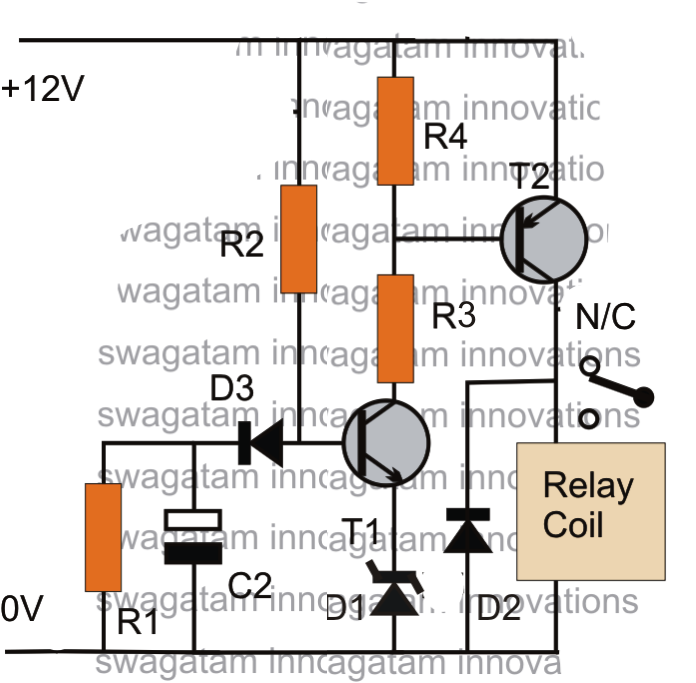
Circuit delay timer simple circuits transistor electronic explained relay electronics projects time homemade diagram electrical power timing engineering button using
.
.


Time Delay Relay Circuit
Circuit Delay Calculation From Logic Diagram

Circuit Delay Calculation From Logic Diagram

Simple Time Delay Circuit using 555 Timer

IC 555 Delay Timer circuit | Easy timer circuit | on off delay circuit

Time Delay Circuit Diagram

Answered: Using the given delays for the circuit… | bartleby